The native data model in Nautobot will suffice for the majority of use cases. However, some deployments have additional requirements between objects based on the design of their networks. Nautobot now provides the capability to define new relationships to support a more customized network data model.
For example, a VLAN may need to be defined on a per-device basis, rather than the native model of a VLAN per site. This would allow a user to define and model VLANs for a network device that are locally significant.
This series of posts will outline the new user-defined relationship feature in Nautobot and explore some use cases where this feature can be applied to help model a network design.
One of the columns in a database table will store a primary key, which will uniquely identify each object. This field is used in the object-relational mapping (ORM) when defining relationships between objects. This simply allows objects to build associations with each other.
A common example used to explain this concept uses books. A publisher has a relationship with a book as it can publish a book. Each book will have a publisher.

Additional constraints can be introduced to be more specific in the relationship definition. The next sections outline the different types of relationships that can exist between objects.
A one-to-many type introduces a constraint in that a book can have only one publisher, denoted with the 1 on line beside the publisher. A publisher can have many books, denoted with N for number on the many side.

A many-to-many relationship has no constraints. A customer can buy many books and a book can be bought by many customers.
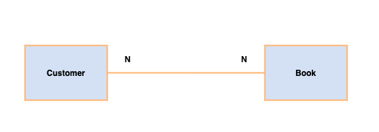
A one-to-one relationship has a unique constraint on both sides of the relationship. For example, an order can have only one payment and a payment can be made on one order.

Nautobot is designed as a Source of Truth application aimed at modeling modern networks. Its core data models allow users to define the intended state of a network. This is achieved by providing a native data model, with its inherent relationships between the objects.
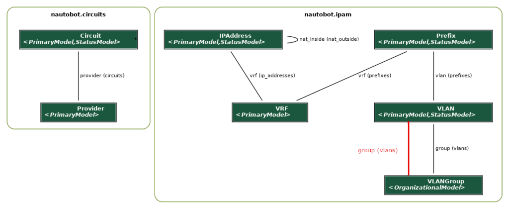
As an example, a subset of the Nautobot core data model illustrates the relationships between some of the objects in the nautobot.ipam and nautobot.circuit applications. The database tables are represented as boxes including their fields. The lines between the tables denote an association or relationship between the tables. The diagram shows how an IPAddress can have a VRF, a Prefix can have a VRF and a VLAN, and finally a Circuit can have a Provider. At a database level, we can see that these relationships are represented as foreign keys between the database tables.
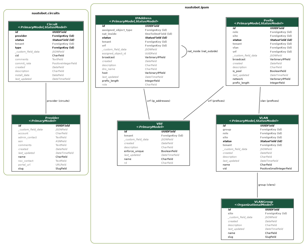
INFO: This diagram was rendered using the graph models feature in the
django_extensionspackage.
The core data model is quite established, based on years of iterative open-source development that began with the NetBox project. However, it’s very difficult to provide a standard framework that can meet the requirements of all networks. There will always be components of the network that will be different. One of the key objectives of Nautobot is to provide maximum data model flexibility. This is where the new Relationships feature can be applied. It allows users to define their own relationships between the objects in the system.
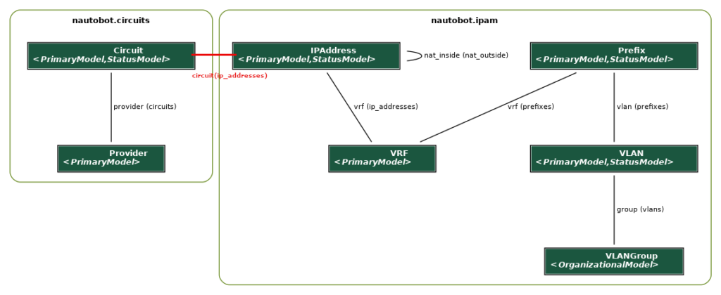
The first use case will focus on modeling an IPv4-based circuit, such as an enterprise router connection to an Internet Service Provider WAN. Each circuit can have two IP addresses, one at each end of the circuit. This type of relationship is not defined in the native data model. To enable it, a new relationship (highlighted in red) can be created between an IPAddress and a Circuit.
To create a new relationship, navigate to Extensibility -> Relationships on the Nautobot web user interface. The use case in question supports one circuit having two IPs. Any model that can have more than one object in the association is defined as a many in the relationship. Enter a custom name to identify the new relationship and set the relationship type as One to Many.
The Source type is circuit | circuit as this is the one side of the relationship and it is defined as the source. The Source Label will be used to display the other end of the relationship, on the source page. For this use case the Source Label is IP Address. The Destination fields are the reverse of the Source fields. Both source and destination filters can be left blank.

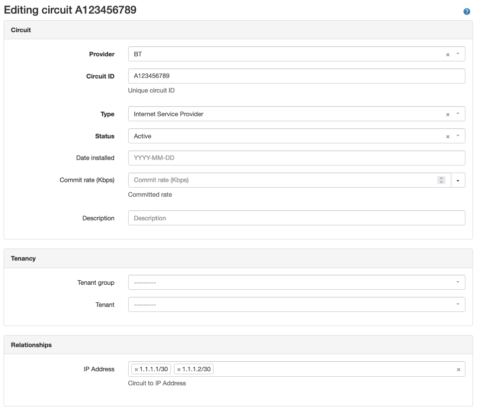
Once a relationship has been created, it will be visible when configuring one of the model objects. A new Relationship panel will be available to select an existing object of the defined source/destination type.
In the example, circuit A123456789 has two IP addresses associated with it. Multiple IPs can be can be selected since IPAddress is on the many side of the new relationship.
For the IP addresses, one circuit can be selected in each IP address object. The selection drop-down list will only allow one object to be configured, as Circuit is on the one side of the relationship.

Defining a new relationship allows network design use cases to be managed through the web user interface by creating new associations between existing objects. This reduces the need to manage additional layers of data by adding custom fields to objects and maintaining the custom field data synchronization through scripts or playbooks. Relationships can also be defined using the REST API.
An alternative solution for this use case might involve creating a one-to-one relationship between an IP Address and Circuit. In this case, a circuit would be associated with one IP Address. Creating two of these associations would model the circuit end-to-end.
Another, perhaps more advanced, use case would be to create a relationship between models that already have a native relationship. For example, a VLAN group and VLAN have an inherent One to Many relationship, whereby a VLAN Group can have many VLANs but a VLAN can only be a member of only one VLAN group. Some networks may have a need to have VLANs in multiple VLAN groups. VLANs could be members of a management group for a site, while also being part of a group that requires access to cloud-based Operational Support Systems (OSS). This use case could be managed with custom tags or custom fields, but relationships provide a way to overlay a new association between the models and link existing objects together.
The diagram below illustrates how the new relationship (highlighted in red) would be modeled, alongside the existing relationship.
A Many to Many relationship is required to support this use case. Following on from the guidelines in the previous use case, with the addition of a filter to restrict the relationship to VLANs with the role of leaf, filtering is defined using JSON data format to identify the model fields and their values.
In the example, the new relationship will be applied only on VLANs that have a role of leaf. Roles can be applied to VLANs to assist with network design modeling e.g., define leaf-switch VLANs.

For demonstration purposes, a short list of VLANs shows some Leaf and Core roles to illustrate the filtering capability.

Editing a VLAN allows multiple VLAN groups to be associated with a single VLAN through the newly defined relationship. A key point to note is that the new relationship is managed through the Relationships panel and not through the native Group field, which is left blank.
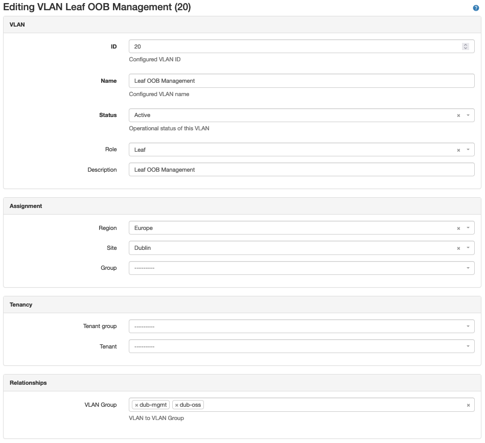
For VLAN group(s) configured in the relationship, apply the new VLANs. Due to the filtering applied on the VLAN side of the relationship, only VLANs with a role of Leaf can be selected.

Management of the new VLANs is through the Relationships panel on the VLAN Group page. For this advanced use case, the native VLAN view (right-hand side) on the VLAN group page is not populated.

Selecting the VLANs hyperlink displays all of the VLANs through the relationship-association table.

Defining new relationships is a very powerful feature in Nautobot. It supports flexible data modeling to assist with specific use cases of network design representation in a Source of Truth application.
This guide focused on how to define the relationships in the web user interface. In a future post, we’ll look at using REST and GraphQL based APIs to interact with the new relationships in Nautobot.
-Paddy
Share details about yourself & someone from our team will reach out to you ASAP!